Integrating with Max
Now that we’ve seen how to make a simple module with a knob and some audio inputs and outputs, let’s continue with all that is possible in Eurorack-blocks. There is a lot of different controls you can use on your front panel, and this list will grow! Mapping those controls to your gen patch is quick, and you have very little to know. Actually, you already know most of it.
First, we will have a quick look at erbui, a simple language to describe your Eurorack module front panel. We plan to make a GUI editor (coming soon), but for now you need to use this language. And even if you are using the GUI editor, it might be handy to make quickly some touch-ups.
Second, we will see how to map the inputs and outputs of your gen patch to the inputs and outputs on your module front panel. You already know most of it with the previous tutorial. We just need know to talk about CV out and LEDs for example, but the principle is the same. We will talk also about how to nicely map for example a knob that is supposed to map to a frequency.
Finally, we will see how to use samples into your gen patch. It’s quite simple too, and we have another language for that, erbb, which describes what sources and resources you use and where they are.
Quick Look at Erbui
We will go quickly on this part, as we plan to make a GUI editor (coming soon). With the
GUI editor, learning erbui becomes quite superfluous.
erbui is a declarative domain specific language used to describe a module user interface.
It is mostly a collection of control elements, with each control representing a physical
piece of hardware on the panel. For example you can have a control for a pot and its knob,
a control for a button, but also a control for gate inputs and outputs, CV inputs and outputs,
audio inputs and outputs, or even LEDs with either one or multiple colors.
Position and style
Every control has at least a position and optionally a style attributes, for example:
control sync_button Button {
   position 2hp, 75.3mm
   style ck, d6r, black
}
The first argument of the position,
2hp expresses the distance between the left side of the front panel to the center of the control,
on the horizontal axis.
Similarly, 75.3mm, expresses the distance between the top side of the board to the center of the control,
on the vertical axis.
Those distances always come with a unit, like hp, mm or cm.
A hp is the Doepfer defined
Eurorack HP distance, which defines 1HP = 5.08mm.
The arguments of style, ck, d6r, black, define the hardware component to use.
Here, ck, d6r, black denotes the
C&K D6 series,
variant R (round button), in black color.
The style is dependent on the control type, here Button. For each control type, you can
visit its control reference, which lists the available styles. For example here is the control
reference for Button.
Label

An optional label can be added to the control. This will be shown on the front panel, for example:
control freq_pot Pot {
   position 6hp, 34mm
   style rogan, 6ps
   label "FREQ"
}
This will place the label automatically below the pot, while taking into account here the size of the knob attached to the pot.
The default label positioning is dependent on the parent control. For example for the jack connectors, the default placement label placement will be done on the top of the control.
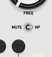
The label positioning can be customized, and even multiple labels can be associated to the same control, for example:
control mute_hp Switch {
   position 6hp, 62mm
   style on_on
   rotation 90°ccw
   label "MUTE" { positioning left }
   label "HP" { positioning right }
}
That’s it. This is mostly what you need to know. If you are adventurous, you may want to read the Erbui grammar!
Mapping Names
As you may have seen, the main concept to map a gen patch input or output to a front panel control is to give them the same name. Depending on the type of the control, there are slightly different boxes to use in your gen patcher. Let’s go through them now:
Audio inputs
AudioIn on your panel is mapped to in <n> in your patcher
where <n> is the index of the input, starting from one. The index follow the order of
declaration in your Erbui file, so if you have the following file:
control audio_in_left AudioIn {
   position 2hp, 111mm
   label "IN L"
}

control audio_in_right AudioIn {
   position 4.66hp, 111mm
   label "IN R"
}
Then in 1 would map to audio_in_left and in 2 to audio_in_right.
Note that the control names are just ignored in the gen patcher, just the order counts.
Yet, it is still important to have the same number of audio inputs in both files. If this is not the case,
the Erbui transpiler will report an error.
One neat thing you can do with audio inputs, is to cascade them. For example using the
previous example, you might want your right audio input to take the left audio input, if the
right audio input is not connected. You can do this simply using the normalling keyword:
control audio_in_left AudioIn {
   position 2hp, 111mm
   label "IN L"
}

control audio_in_right AudioIn {
   position 4.66hp, 111mm
   normalling audio_in_left
   label "IN R"
}
Audio outputs
AudioOut on your panel is mapped to out <n> in your patcher
where <n> is the index of the output, starting from one. The index follow the order of
declaration in your Erbui file, so if you have the following file:
control audio_out_left AudioOut {
   position 7.33hp, 111mm
   label "OUT L"
}

control audio_out_right AudioOut {
   position 10hp, 111mm
   label "OUT R"
}
Then out 1 would map to audio_out_left and out 2 to audio_out_right.
Note that the control names are just ignored in the gen patcher, just the order counts.
Yet, it is still important to have the same number of audio outputs in both files. If this is not the case,
the Erbui transpiler will report an error.
Input controls
CvIn, GateIn, Button,
Pot, Switch and Trim on
your panel are all mapped to param <name> in your patcher
where <name> is the name of the control in your Erbui file.
So if you have a param freq box in your gen patch, then you will need a
control freq definition in your Erbui file.
The mapping also supports gen param attributes @min and @max.
GateIn and Button represent on or off values
that are mapped to the minimum and maximum value of the gen parameter, respectively.
In the case of the Switch, the intermediate value is mapped to the
average between the minimum and maximum of the gen parameter.
Output controls
CvOut, GateOut, Led,
LedBi and LedRgb on
your panel are all mapped to history <name> in your patcher
where <name> is the name of the control in your Erbui file.
LedBi and LedRgb are a bit special though,
because they are not represented by one scalar value, but 2 for the dichromatic LED
(one for each component, usually red and green), and 3 for the Rgb LED (one for each
primary colors).
In this case you need to address the specific property to set in the control, by appending
an underscore _ and the name of the property.
For example, if you have the following Erbui description:
control state_led LedBi {
   position 7.33hp, 85mm
}
To set the value of the red portion of the led, you would use history state_led_r and similarly for the green portion, history state_led_g.
Important
When using output controls, make sure that the control name in Erbui
doesn’t end with a digit! Just give it another name, or append a _ character.
Jack Detection
AudioIn, CvIn and GateIn
supports jack detection by specifying the normalling nothing property:
control clock GateIn {
   position 7.33hp, 85mm
   normalling nothing
}
You can then use param <name>_plugged in your patcher
where <name> is the name of the control in your Erbui file. The value will be 1 if and only
of a jack is plugged into the physical input.
In the example above, you would have a param clock_plugged box in your gen patch.
Important
Make sure to ignore the values of the input control when it is not plugged, as it is noise.
That’s it, this is all you need to know about how to map your front panel controls to your gen patch. Eurorack-blocks takes care of all the rest!
Mapping Values
Now that we know how to map a name, we need to know how to map the value associated to that name. It’s quite easy indeed.
In Erbui, all values are unipolar, meaning they range from 0 to 1. But you can make them
bipolar, so that when the knob is at the middle, it is equivalent to 0. This is only handy
when using the simulator, as the knob will be centered by default. You specify a bipolar
control using its mode. You typically use this for a trim pot that used as an
“attenuverter”:
control feedback_trim Trim {
   mode bipolar
   position 7.33hp, 80.8mm
   label "–/+" { positioning top }
}
On the gen patch side, you just need to specify a minimum and maximum value, and
Eurorack-blocks will map it accordingly. The bipolar mode has no effect on that.
If your pot is on the most-left side of its angular rotation, the value of a parameter will
be the @min value of your gen param box, 0 by default if you didn’t specify it.
Similarly, if your pot is on the most-right side of its angular rotation, the value of a parameter will
be the @max value of your gen param box, 1 by default if you didn’t specify it.
Though it is usually easier to keep the default minimum and maximum values to 0 and 1 respectively, which allows you to scale the param nicely to accomodate for human perception. For example, to scale a frequency pot, you can use the box expr out1 = 10 * pow (22000/10, in1) which will output a value of 10Hz when the pot is on the most-left side, 22kHz when the pot is on the most-right side, while following a natural perceptual progression for the values in between.
Using Samples
The last point to see is how to use samples in your patch, and Eurorack-blocks makes this task very easy! The samples are defined in the build-system file together with your source code — here just your max patch. You just need to define an audio sample, give it a name and the file path relative to your erbb file.
Important
Adding a sample is done in your .erbb file, not the .erbui file!
module Kick {
   sources {
      file "Kick.erbui"
      file "Kick.maxpat"
   }

   resources {
      data kick AudioSample { file "kick.wav" }
   }
}
You just need to add a resources scope and add as many — reasonably though! for a
reason we will see below — data declaration as you have samples.
Then you can simply add the sample in your gen patch as a
data <name> 0 <channels> box, where,
you guessed it, <name> is the name of the data in the Erbb file, so for example
data kick 0 1 in the example above. That’s it!
A value of 0 seems weird for a data length, but that’s because Eurorack-blocks will change
automatically for you, to match the size of your sample.
You might now think, but where are those samples stored? For both the simulator and the firmware, this is stored in the program itself. For your module running in the simulator using VCV Rack, this is not a big issue. The files can be quite large but will run happily. If you put large files though, you will see that building the module will take more time. Though, for the final firmware, things are not so ideal. We have 2 choices here.
Either store the program in the so-called FLASH memory, which is 128K, so there is really not much room. But if you have a few wave tables to store, that might make it.
If you are going passed this point, we can store it in another memory, called the QSPI
memory, which has a more ample 8MB to work with. So you can’t really store a full song,
but if it’s for drum samples and the like, that should totally work.
To use this memory instead you need to add a section qspi in your Erbb file:
module Drum {
   section qspi

   sources {
      file "Drum.erbui"
      file "Drum.maxpat"
   }

   resources {
      data kick AudioSample { file "kicks/kick_aba.wav" }
      data kick2 AudioSample { file "kicks/kick_ece.wav" }
      data hat1 AudioSample { file "hihats/hat_01.wav" }
      data hat2 AudioSample { file "hihats/hat_02.wav" }
      data ride AudioSample { file "rides/ride.wav" }
   }
}
Uploading the firmware is then a bit different, but this whole process is explained in great details in “Kick: Samples & Big Programs”.
That’s it! This is all you ever wanted to know about Eurorack-blocks and Max integration. Happy patching 🎉