Assembling Demo Modules
The Starter Kit comes with two demo modules: Drop which is a stereo DJ filter, and Frohmager which is a multi-band resonant filter.
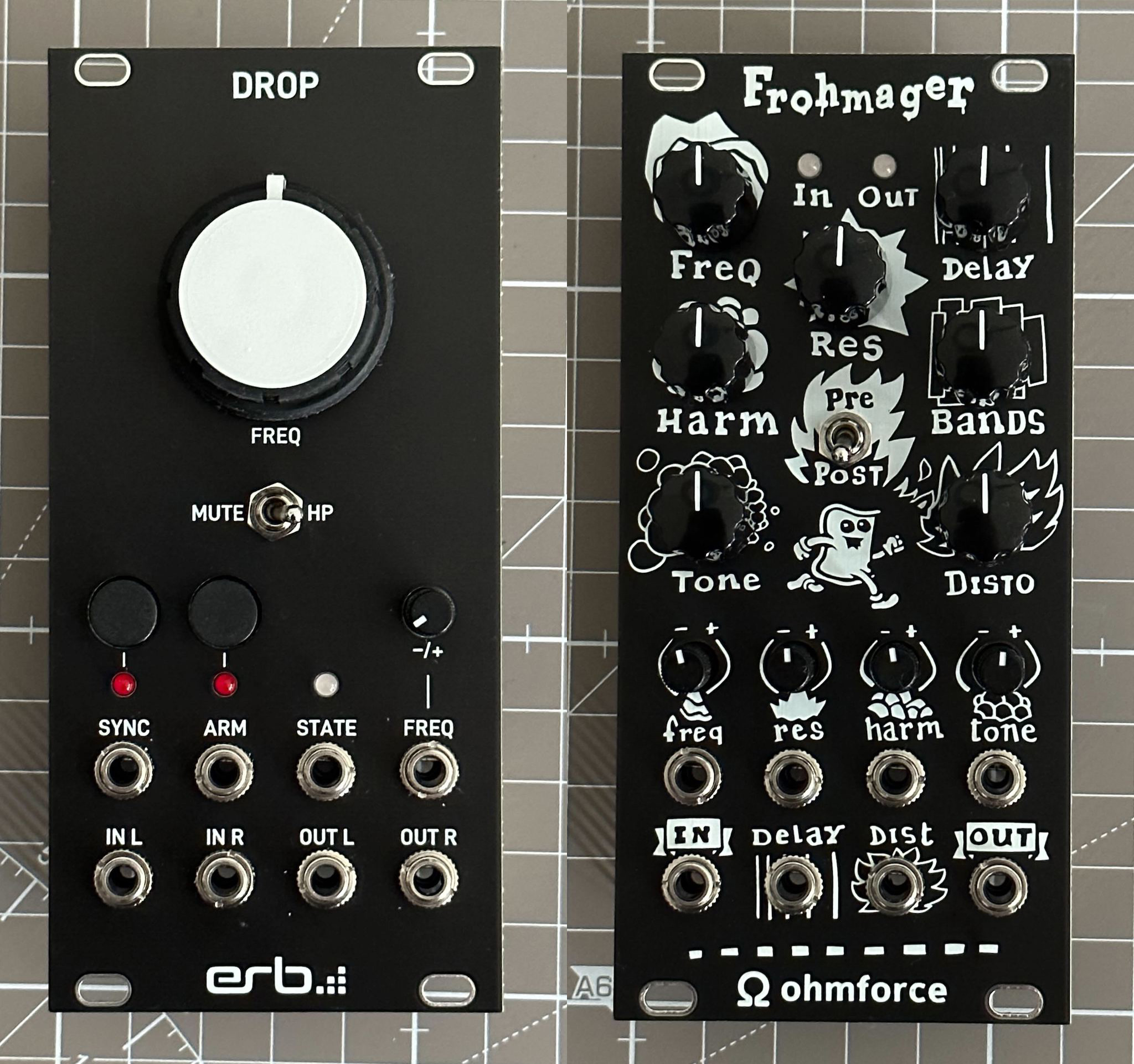
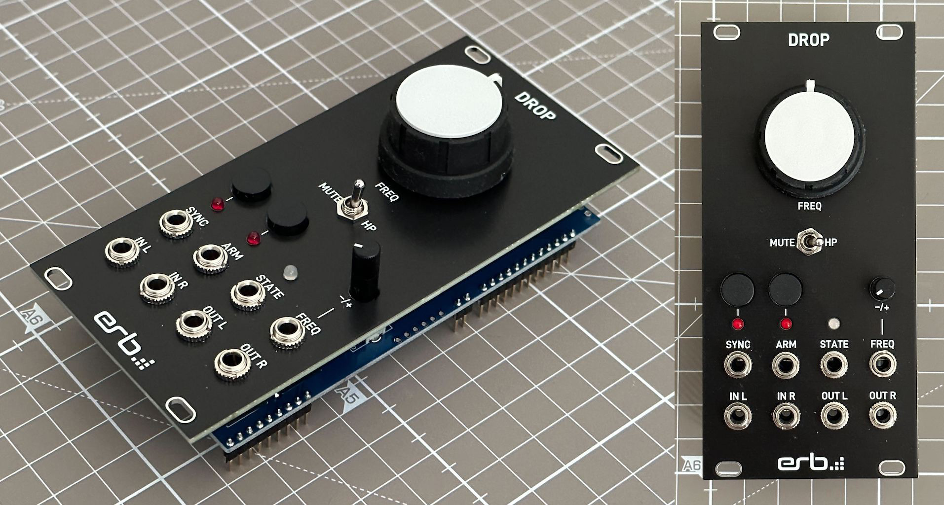
Fully assembled Drop and Frohmager front panels.
Frohmager
Let’s start with the most fun one, that is maybe the easier one as well.

Take:
2 2-position pin headers,
1 4-position pin headers,
3 8-position pin headers,
1 9-position pin headers,
1 10-position pin headers,
1 12-position pin headers,
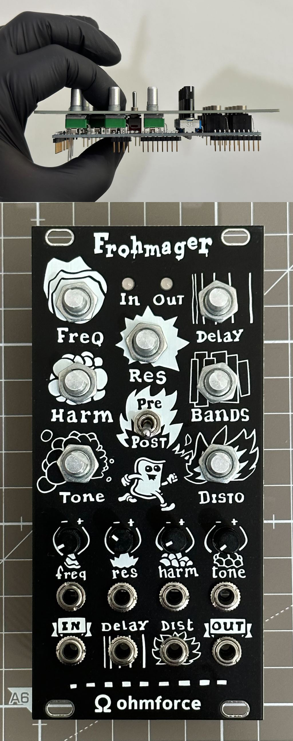
And place them in the pin sockets as shown in the picture on the right.
Note that not all pin sockets are populated ⚠️ In particular we don’t need the pin headers for the first 8 buttons/gates labelled from B1 to B8, neither the SD card pins.
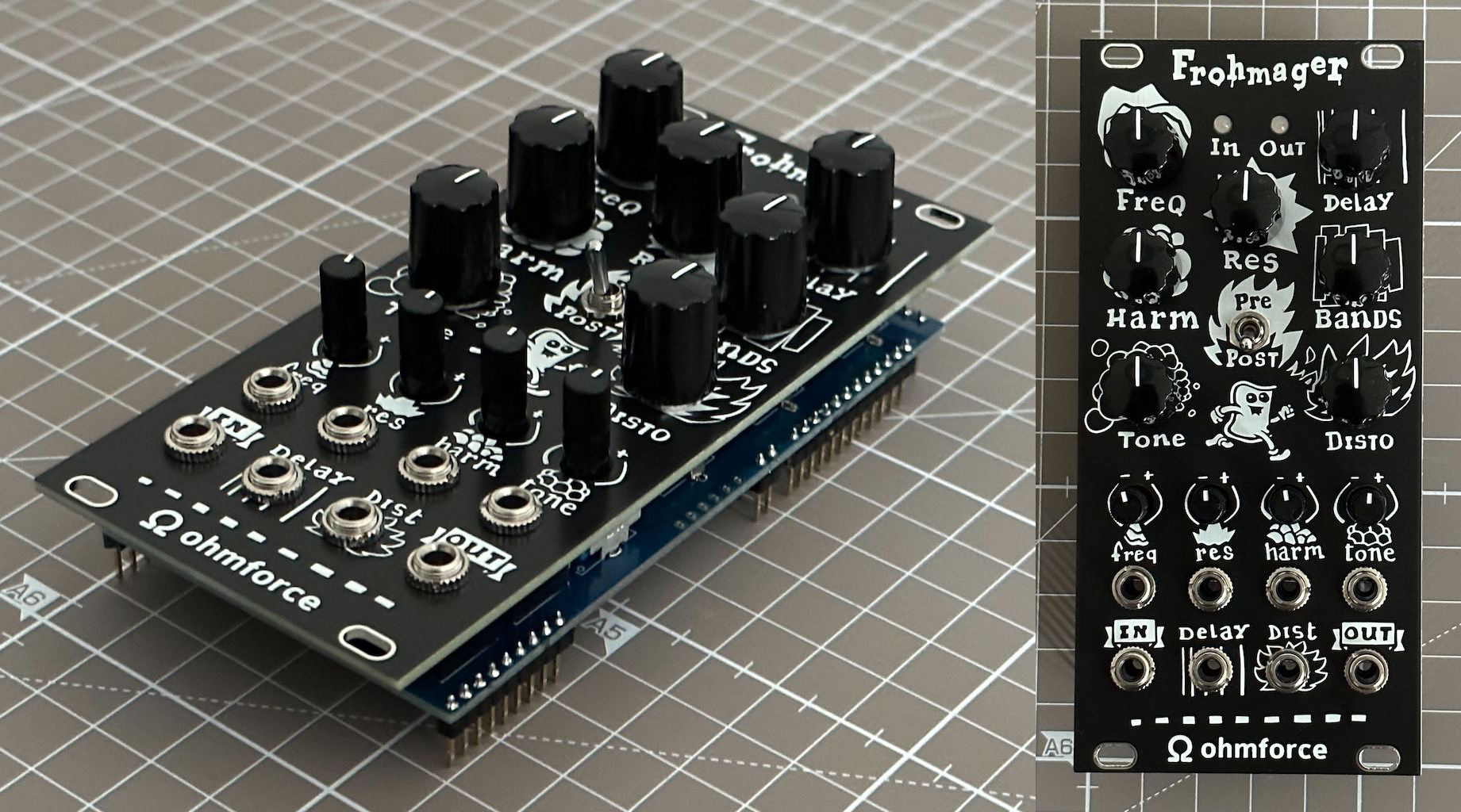
Put the Frohmager PCB on top and make sure that everything is proper and flush. Then solder all the pins.
Once done you can remove the front panel from the Kivu12 board.
Warning
Be very careful when removing the front panel from the Kivu12 board to not bend the front panel pins! ⚠️
Take your time, and always keep the two boards parallel.

Place all the components on the board, but do not solder anything yet!:
For the LEDs, the shortest leg goes into the hole on the right,
Screw in the nut of the switch like on the picture, and try to balance the switch tip between the 2 extreme positions, like shown on the picture. This will help putting the front panel later.
Do not solder anything yet!
Now insert the front panel, align it so that everything is properly centered. You want to make sure to always keep the front panel and PCB together, or the pins of the jack connectors will slip out, which can be quite frustrating!
Secure the potentiometer on the panel using the supplied nuts. Do the same for the jack connectors and the switch. Make sure all the nuts are properly tighten up ⚠️ Push the LEDs so they fit properly into the panel holes.
Inspect one more time on the front and side to make sure everything is properly aligned.
Solder all the parts. Before soldering the LEDs, make sure again that they fit properly in the front panel holes.
The LEDs are also the most sensitive part of this build, so do not apply heat more than 2 seconds, and give it some time to cool down before trying again.
Once everything is soldered, grab your wire cutter and cut the excess wire part of the LEDs.
Now secure all the pot, switch and jack connector nuts, and finally put the black knobs. It’s done! 🎉
And now it’s time for a quick testing! We’ll upload the firmware, so you can play a bit with your shiny new Frohmager module before we continue with the Drop module.
Download this firmware file, and head over to the Daisy Web Programmer using the Google Chrome Browser.
Connect a USB cable to the Daisy Patch SM, which will turn on its LED. Enter the system bootloader by holding the BOOT button down, and then pressing, and releasing the RESET button. Press the Connect button on the Daisy Web Programmer and select “DFU in FS Mode”. Then click the button “Choose File” in the “Select a file from your computer” section, and finally click the “Program” button. Wait a bit and tada, the program will be uploaded.
Important
When this procedure doesn’t work, 99% of the time this is because of a faulty USB cable, so make sure you are not using a “charging USB cable”, or just take another one, just in case.
Now disconnect the USB cable, put your Frohmager module in your rack and connect it to your case power, and turn it on.
It’s now time to take a break and have a good time with your Frohmager module!
Ah! and something neat: if you decide to reuse the Frohmager panel to make your first modules, we made the panel so that it’s symmetrical. This means you can turn it the other way around, which allows you to start with a blank panel, and use a small chalk marker to design your front panel (to keep track which control is what) 🤯 How cool is that?
Drop
The Drop module has a bit of everything, so when you manage to solder this module, you will know about all the different parts you will commonly use in Eurorack-blocks!

Take:
2 2-position pin headers,
1 4-position pin headers,
2 8-position pin headers,
1 9-position pin headers,
1 10-position pin headers,
1 12-position pin headers,
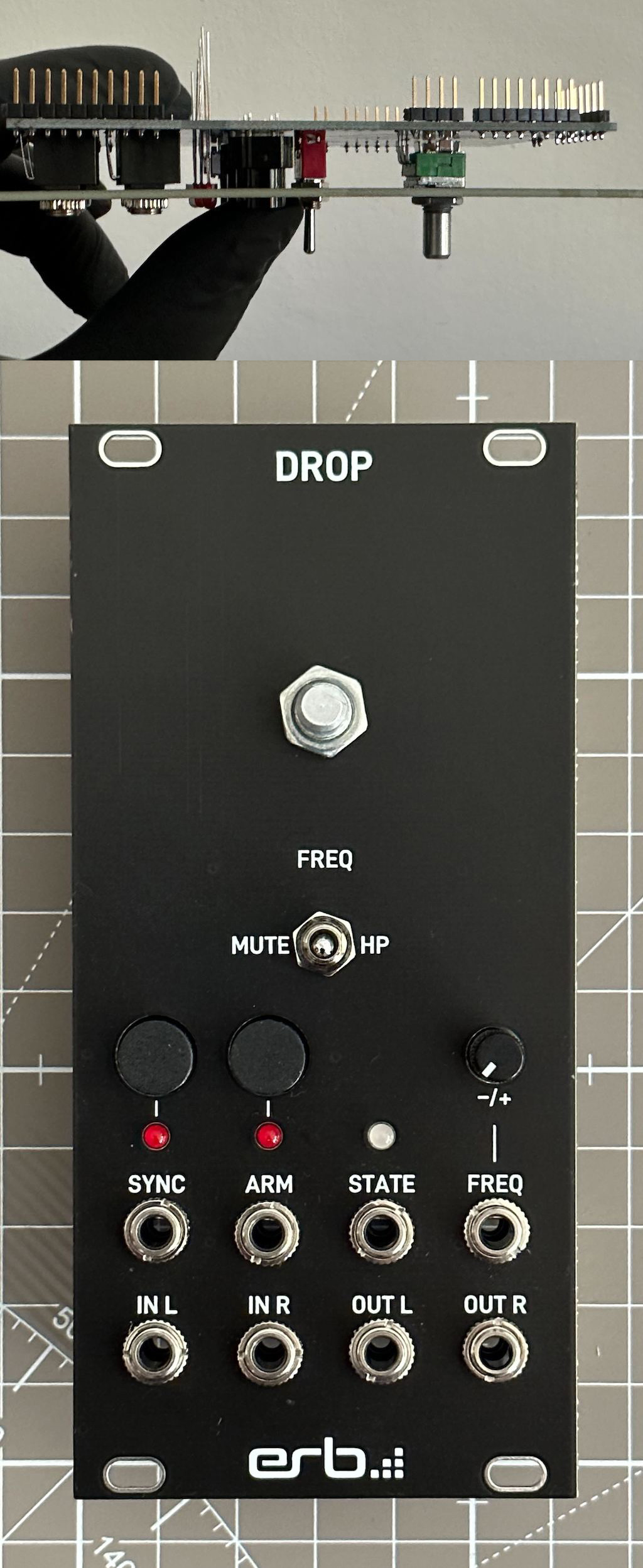
And place them in the pin sockets as shown in the picture on the right.
Note that not all pin sockets are populated ⚠️ In particular we don’t need the pin headers:
For the 8 buttons/gates labelled from B9 to B16,
nor the LED pins labelled from L9 to L16,
nor the SD card pins.
Put the Frohmager PCB on top and make sure that everything is proper and flush. Then solder all the pins.
Once done you can remove the front panel from the Kivu12 board.
Warning
Be very careful when removing the front panel from the Kivu12 board to not bend the front panel pins! ⚠️
Take your time, and always keep the two boards parallel.

Place all the components on the board, but do not solder anything yet!:
Put the LEDs in their hole, and double check their orientation.
For the 2-pin red LEDs, the shortest leg goes into the square-shaped-pad hole on the left,
For the 3-pin LED, the shortest leg goes into the hole on the right.
Put the nut for the switch like for Frohmager, and try to balance the switch tip between the 2 extreme positions. This will help putting the front panel later.
Put the 2 push-buttons and observe the flat side of the button ⚠️ and match it to the flat side on the PCB silkscreen, on the left of the button in the picture.
Do not solder anything yet!
Now insert the front panel, align it so that everything is properly centered. You want to make sure to always keep the front panel and PCB together, or the pins of the jack connectors will slip out, which can be quite frustrating!
Secure the potentiometer on the panel using the supplied nuts. Do the same for the jack connectors and the switch. But this time, make sure all the nuts are not too tight ⚠️
Inspect one more time on the front and side to make sure everything is properly aligned.
Solder all the parts, except the LEDs first. Before soldering the LEDs, make sure again that they fits properly in the front panel holes.
The LEDs are also the most sensitive part of this build, so do not apply heat more than 2 seconds, and give it some time to cool down before trying again.
Now remove all the nuts and remove carefully the front panel.
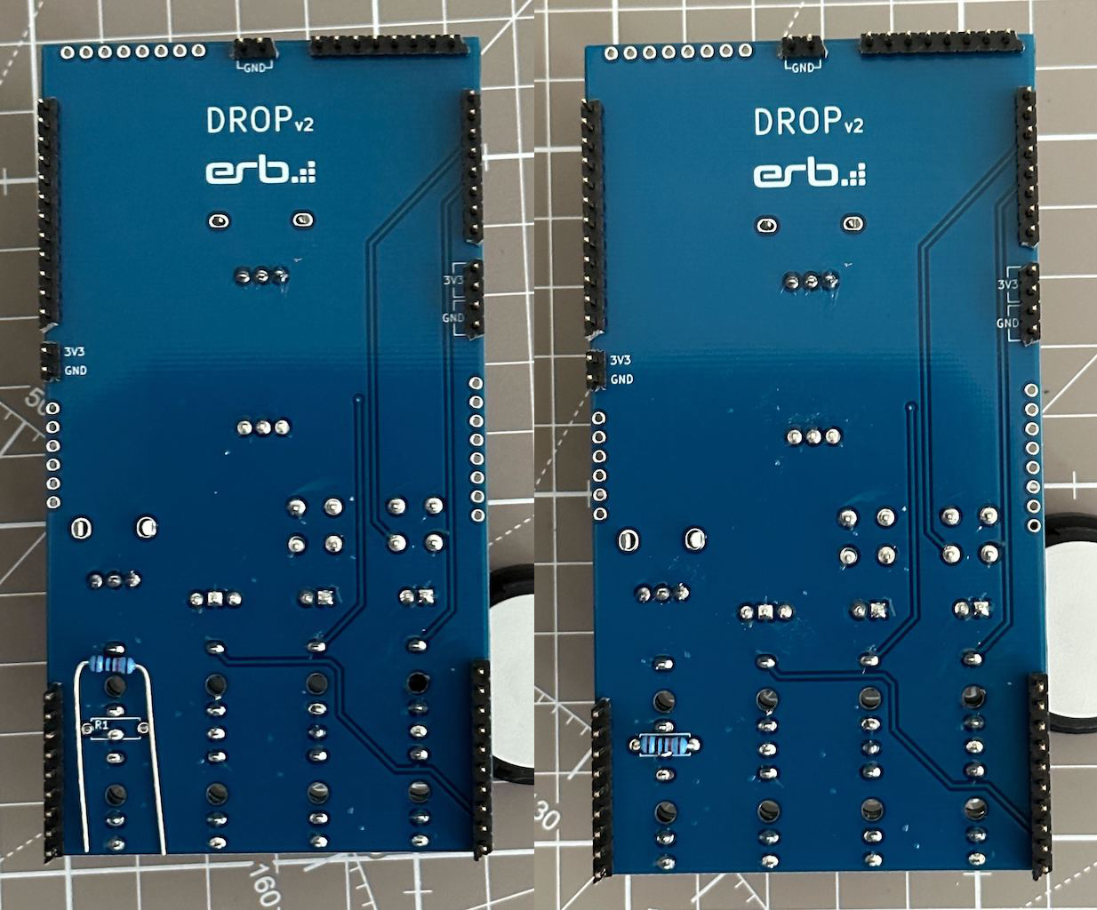
Grab the resistor and bend its pins to match the resistor holes. Then turn the board over, make sure the resistor is flush to the board and solder it. Take your time as it is very tight with the jack connectors around!
Now take your wire cutter and cut the excess wire part of the LEDs and resistor.
Now you can put back the front panel, secure all the nuts properly tighten up this time ⚠️, and finally put the big knob for the frequency potentiometer.
That’s it, you did it! 🎉
To test this module, we will use the Eurorack-blocks environment as shown in the next chapter. Depending on what language you use, C++, Max, we have a project specificly made for it.
It is time now to install the Eurorack-blocks environment on your computer!