Ordering & Assembling the Front Panel
Overview
The front panel consists of a PCB and a panel you need to assemble together. The nuts or screws you have on the jack components or pots are what secure the panel to the PCB.
The panel itself can be produced using either the FR-4 material (the material used in PCBs) or aluminum. FR-4 is cheaper, while aluminum is more expensive but also more robust.
For simplicity of soldering, and making the process more inclusive, all parts are THT components except rare exceptions (when a component is only available in a SMD package, such as some specialties LEDs).
Reviewing Manufacturing Files
Let’s take a look at all the manufacturing files you have generated so far.
eurorack-block/samples/kick/$ ls -l artifacts/hardware/
total 968
-rw-r--r--   1 raf  staff    1198 Feb 17 09:07 Kick.bom.csv
-rw-r--r--   1 raf  staff   17781 Feb 17 09:07 Kick.dxf
-rw-r--r--   1 raf  staff  113944 Feb 17 09:07 Kick.gerber.zip
-rw-r--r--   1 raf  staff  338644 Feb 17 09:07 Kick.kicad_pcb
-rw-r--r--   1 raf  staff   15965 Feb 17 09:07 Kick.pdf
drwxr-xr-x  12 raf  staff     384 Feb 17 09:07 gerber
Kick.bom.csvis the Bill of Materials (BOM) of the components you need to buy,Kick.dxfis the CAD file used by the milling/drilling machines for your front aluminum panel,Kick.gerber.ziprepresents the PCB informations for the manufacturer. You typically upload this file to your PCB manufacturer,Kick.pdfis the PDF file to print your design (usually using the UV printing technology) on your front aluminum panel.
Ordering the PCB
Go to your favorite PCB manufacturer, here Beta-layout in Europe,
and use the Kick.gerber.zip file
(usually using drag & drop), to upload the PCB gerber files.
Depending on your PCB manufacturer, this shoud look like this:
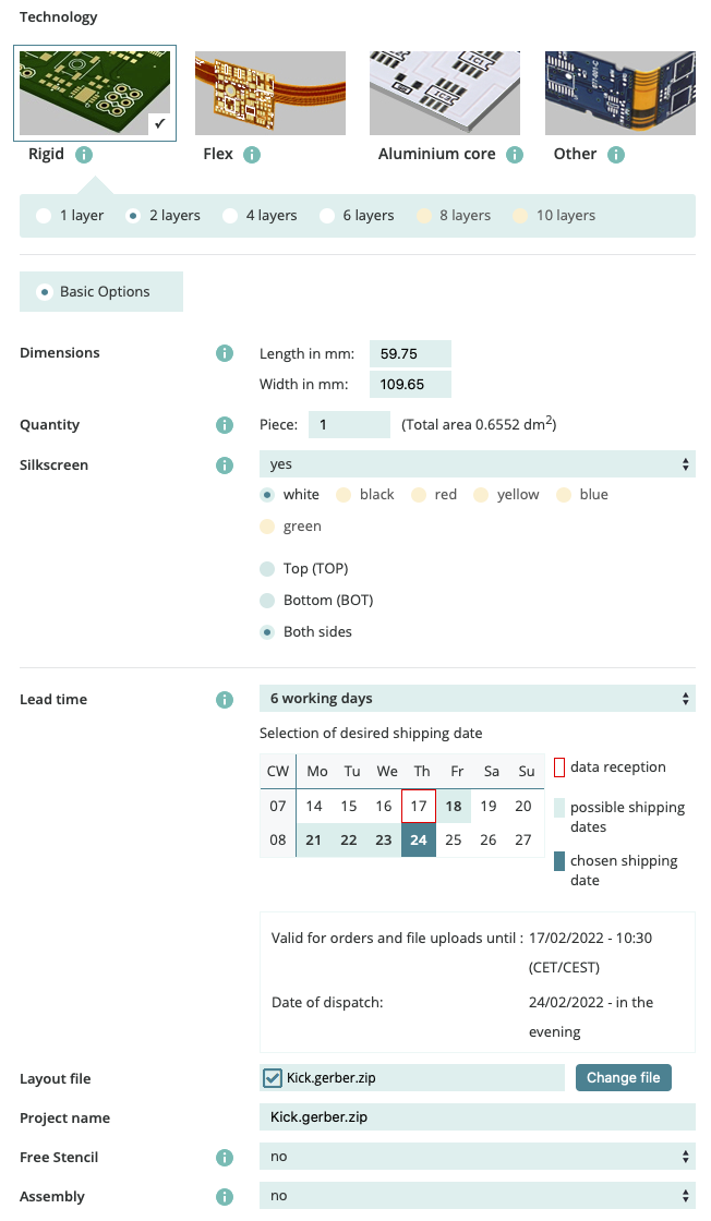
Make sure that:
You are ordering a 2-layer board,
The height is around (but very closely to) 109.65mm,
The silkscreen is printed on the Both sides.
Then the amount of boards is up to you. Usually getting at least 5 boards is a good idea, so maybe first talk with friends to know who would want some!
The PCB manufacturer shown upper is producing the PCB in Germany. If you are living in Europe, this is very handy because you don’t need to deal with long delivery times and customs processes. However that also comes at a higher price!
If you want to save on that, you can produce abroad, for really cheaper PCB, but at the expense of a longer delivery time. Should you choose this option and the PCB manufacturer offers a DDP option for delivery, go for it! DDP means “Delivery Duty Paid (legally much more as part of incoterms) and saves you a lot of time potentially when dealing with customs, and the import taxes are pre-paid by the transporter, saving yet more time when receiving the package.
Ordering the BOM
Open the BOM CSV file in any spreadsheet application. It should look like this:
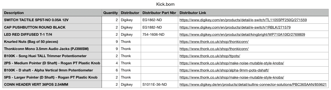
The first column contains the description of the part. Sometimes the shop page for a part has different variants, so make sure to select the one matching the description!
The second column contains the quantity for one board. Make sure to multiply this number with the number of assemblies you want to build!
Finally the last column contains the link to the shop page.
The process is generally to open the shop page in your browser, make sure to select the proper variant as listed in the description column, and put the quantity you have in your BOM multiplied with the number of modules you want to build.
Though in practice, it is a good idea to order more and to have some stock for your next module. To simplify this task, we crafted a nice bundle package (coming soon) with Electrosmith: it is made so that on average, you would have enough part to create 5 modules. Buying 2 of those bundles shoud last for some time! And since Electrosmith is also the producer of the Daisy Patch Submodule, you can conveniently order your entire module parts in one single place. Isn’t that nice?
Ordering the Front FR-4 Panel
The cheapest way to produce a front panel is to produce it like a PCB, using the FR-4 base material. Typically, you would order it with a black solder mask, and white silkscreen.
For this you need to specify the pcb material:
// Kick.erbui

module Kick {
   width 12hp
   board kivu12
   material pcb
   header { label "Kick" }
   ...
}
To order this, follow the same procedure explained upper in “Ordering the PCB” but load
the Kick.panel.gerber.zip file instead.
Then you might want to select black fo the solder mask color (sometimes called just “PCB color”) and white for the silkscreen color.
This would be typically look like this, here illustrated using the JLCPCB service in China:
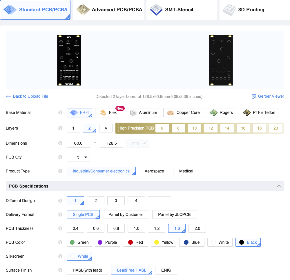
Note
By default, PCB produced by JLCPCB have a surface finish that contains lead. This requires special handling (you cannot just put the PCB to the trash). Instead, use their “LeadFree HASL” surface finish, which is bit more expensive but less dangerous, as shown in the screenshot above.
Note also that technically, one should order the PCB with a 2mm thickness to comply with the Eurorack mechanical specifications, but this is a lot more expensive, and 1.6mm is good enough.
Ordering the Front Aluminum Panel (alternative)
A more expensive option, yet more robust over time is to make the front panel in aluminum.
Go to your favorite aluminum front panel manufacturer, here Schaeffer AG in Europe, and download their front panel software.
Then launch their software, and make a new panel by importing the Kick.dxf file.
Normally you would just accept the default options about units (everything is in millimeters),
and double check that the panel height is exactly 128.5mm.
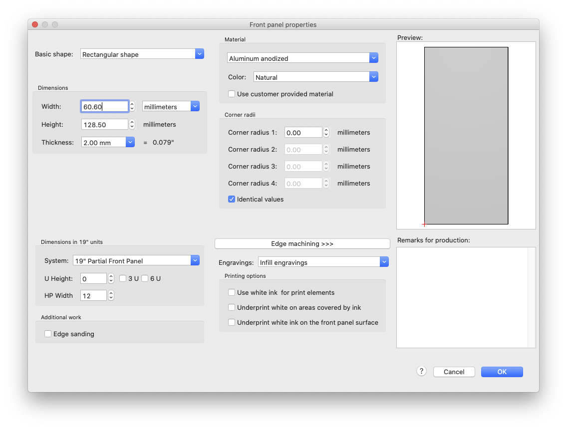
Select a 2mm thickness for the aluminum panel,
Select the Aluminum anodized material,
Select the color matching your Erbui
materialspecification:For
material aluminumyou should choose the Natural color of the anodized aluminum,For
material aluminum blackyou should choose the Black color.
Then add a graphic object to load your Kick.pdf file. The file has been made to exactly
match the panel size, so make sure the absolute position of the graphic design is 0, 0.
This should look like this:
Note
In some cases, you might want to use white ink underprints for your design. Check on the manufacturer website what this option is, to know if you need it, since this is design dependent.
You’re now ready to order your front aluminum panel. Follow the panel manufacturer instructions to order the panel.
Assembling the Front Panel
Gather all your components to make sure you are not going to miss some or search for some later. Put on your lab coat, gather a pair of gloves and safety glasses, and ensure proper ventilation.
You want to ensure perfect alignment between the front aluminum panel and your PCB. For this, one technic is simply to put the components on the PCB, and then put the aluminum panel and use the screws to make sure everything is tighten properly and nicely aligned. It is a bit more tricky with the jack connectors, so you can use some sort of clamp (but don’t put too much pressure!) to make sure your PCB and front aluminum panel are secured while you are soldering. Make sure that your tall trim pots are also sitting nicely in the center of the panel hole, and that you push your LEDs all the way in the front panel before you start to solder.
When all your controls are in place, you can remove the aluminimum panel, and solder on the back of the PCB all the wires, unless you went for the autorouting option explained in a previous chapter.
Finally, remove the aluminum panel, put the pin headers on a breadboard, in a way where you can make sure your board is perfectly vertical to the headers. Put back the front aluminum panel and secure tightly (but not too much!) all the screws.
That’s it! You are done, and you made it! 🎉
The last final step is just to assemble your back board to your front panel carefully (to not bend any pins), do the same with your Daisy Patch Submodule unit, and you are now ready to flash the firmware as explained in a previous chapter and enjoy your very own Eurorack module in your Eurorack system!