Assembling Kivu12
Kivu12 is our 12HP Eurorack motherboard. It is meant to be used for audio digital effects. As so, all the jack connectors are most likely to be placed at the bottom of your module.
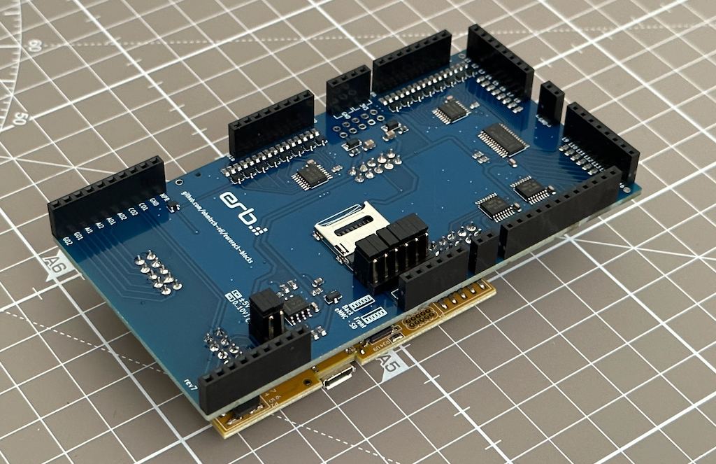
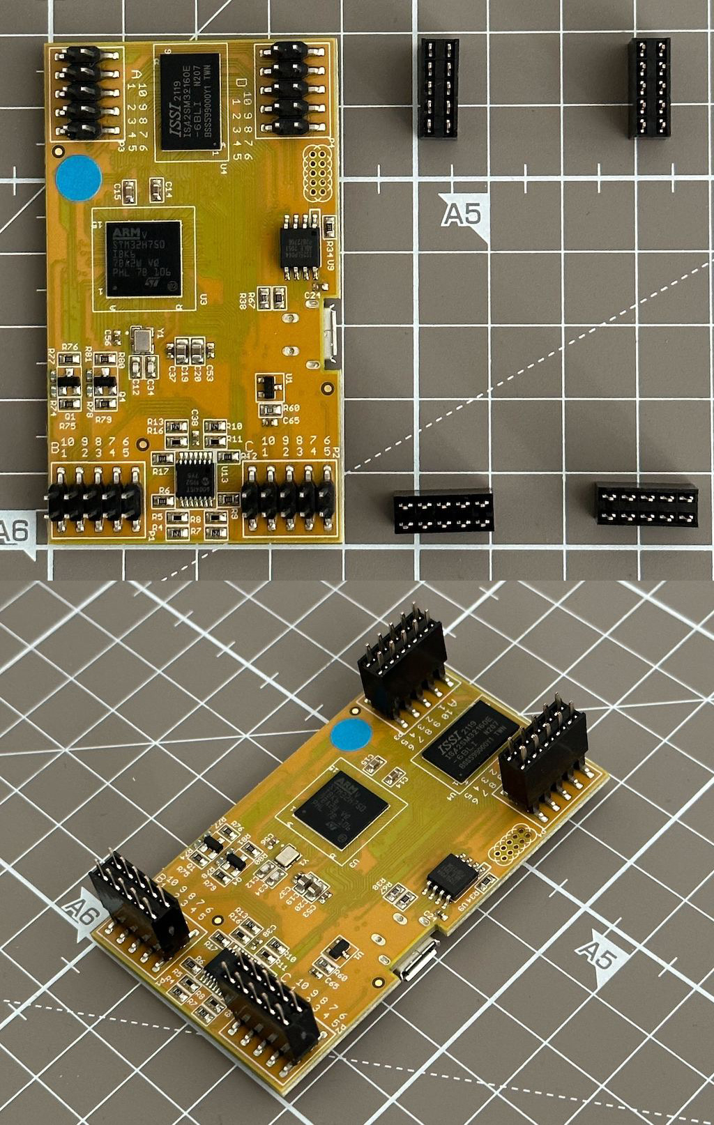
Fully assembled kivu12 board with jumpers configured to use the SD connector on the board, and two first CVs in pitch mode.
Soldering Kivu12 is quite easy. All Surface-Mounted Devices (SMD) are already assembled, so the only thing that is left to do is to solder the pin headers and sockets. The main consideration to keep in mind is to properly align the headers so our future front panel can fit into it without using too much force. This can be done manually by inspecting the pin sockets are flush to the board and aligned visually.
You have two methods to solder the kit:
Either using a rubber band (not included),
Or using our soldering jig (not included).
The rubber band is the most economical way to solder the kit, and chances are you have already some at your place.
The soldering jig, that you can order from ShapeWays separately here, has two main benefits:
If you are unsure about your soldering skills, this is the easiest way to go, as the jig makes sure the headers are properly aligned,
If you plan on soldering many starter kits, this speeds up considerably the whole process.
In the nexts sections we will show how to use those two different methods.
Now, locate the parts bag and take out all the pin sockets and headers.
Important
Avoid touching the SMD components with your fingers if you don’t have an anti-static wrist strap band, and in all cases be very careful not to poke them with your soldering iron tip!
Note
In the following, please click on the pictures to see a bigger version of them.
Glossary
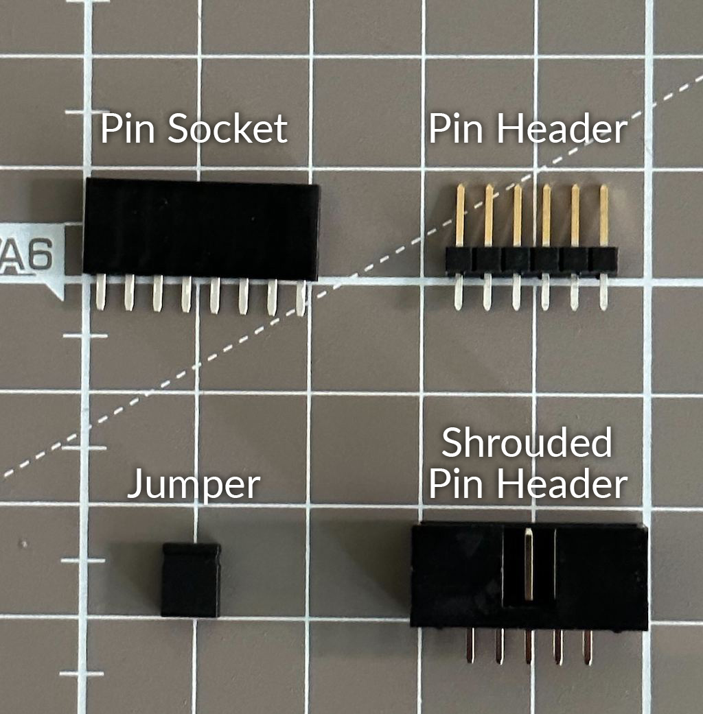
For this build, we are going to use only a few parts from the bag part. We will use pin sockets, pin headers, jumpers and shrouded pin headers. You can associate each terms with what they are in the photo below:
Using a Rubber Band
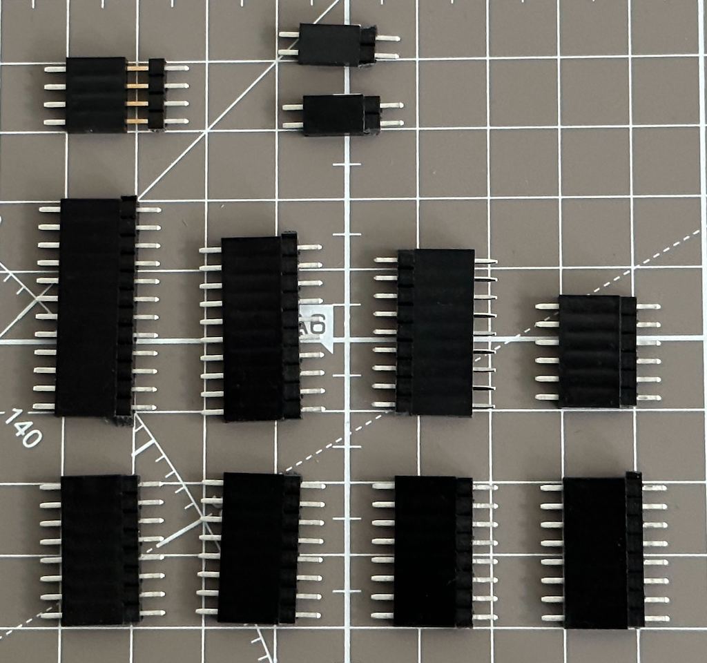
Take all the pin sockets and match them with pin headers with the same number of pins. You will have many pin headers left, this is normal: The pin headers are going on the module panel side, and you have enough pin headers to solder both the Frohmager and Drop modules.
Plug them and make sure there is no gap between the pin header and the pin socket. The photo shows how the 4-position pin socket and header are being assembled. Orient them all in the same direction, for example all pin sockets on the left and pin headers on the right, like in the picture.

Balance the Kivu12 board on top of the Rogan 6PS Knob (that’s the only black and white big knob in the bag of parts), and put your pin socket/header assembly in each respective holes on the sides of the board.
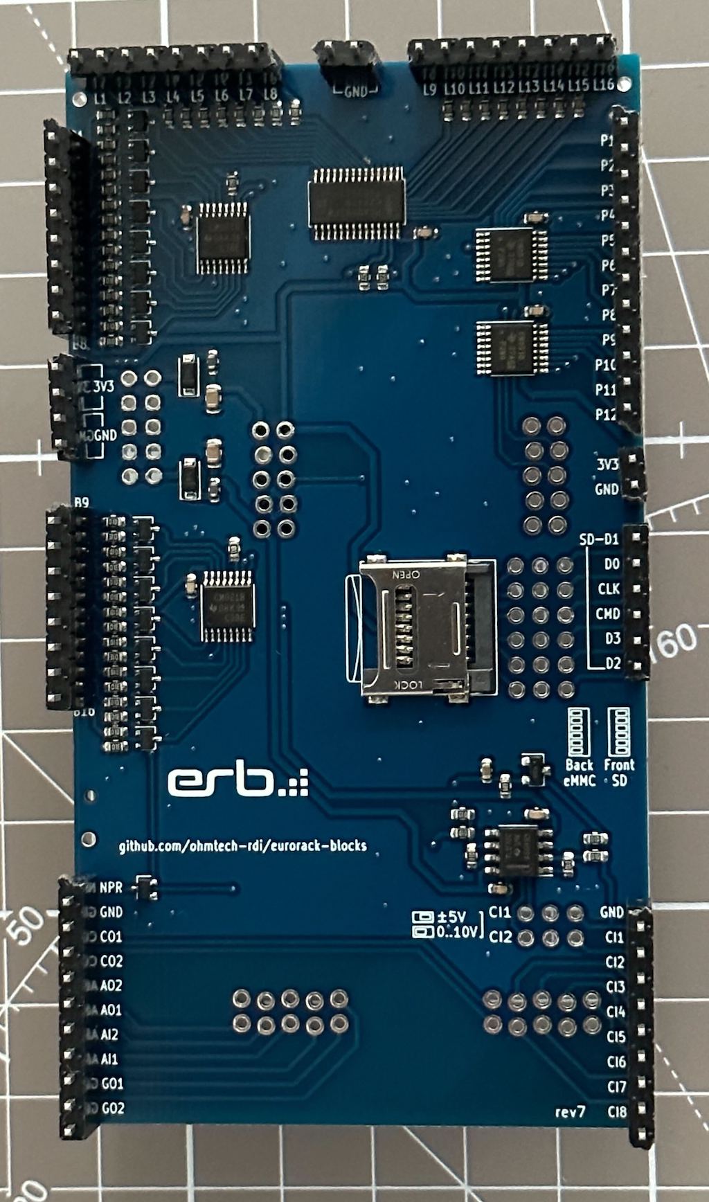
Make sure you see the ERB logo to ensure you are putting the pin sockets/headers on the right side of the board.
Also ensure that the ⚠️ pin sockets ⚠️ are mounted on the ERB kivu12 board, and not the pin headers.

Put one of the demo board on top of this assembly (it doesn’t matter which), and align both boards so that your pin sockets/headers assemblies are secured into each board. Next grab your rubber band and secure this big assembly. Ideally, place the rubber band as shown in the picture, it will be easier to solder pins later.
Finally turn your assembly over and set the big Rogan knob aside, so you are facing the back of the kivu12 board, as shown in the picture. At this stage, you want to make sure that all pin sockets/headers are flush to the board, and nicely perpendicular. Also you want to verify again that the pin sockets are mounted on the ERB kivu12 board, and not the pin headers.
Let us emphasize this one more time.
Warning
⚠️ Be sure to solder the pin sockets on the kivu12 board side ⚠️
Desoldering pin headers or sockets is nearly impossible without proper specialized equipment, so you really want to double check this before soldering!
Now solder all the pin sockets on the kivu12 board side.
When done, put the demo front panel aside and you will get the result as shown on the picture on the right. You can now remove all the unsoldered pin headers from the kivu12 board, that we will use later.
Take the 3 6-position and 2 3-position pin headers and 6 jumpers, and make an assembly as shown in the picture below. This allows to make a block of headers and align them properly.


Then place it on the board as shown in the picture on the right.
Turn the board over and make sure everything is sitting flush. You can check this by ensuring that the tips of the headers you are going to solder are sticking out of the kivu12 board by the same length.
When everything is flush and proper, solder all those pins.
Take the 4 5x2-position pin sockets and place them on the Daisy Patch Submodule.
The kivu12 board has this weird “ziz-zag pattern” for the pin sockets holes that allows to secure the pin sockets on the board while soldering. It’s a tip from Electro-smith and quite a smart one!
Turn the board over and make sure everything is sitting flush. You can check this by ensuring that the tips of the headers you are going to solder are sticking out of the kivu12 board by the same length.
When everything is flush and proper, solder all those pins.

Finally the last soldering step! Find the 5x2-position shrouded pin headers and put it on the back of the board.
Make sure the key of the pin header follows the orientation as shown on the PCB. If you look well on the picture, the key is located on the left.
Because the pin headers of the kivu12 that connect to the SM are the same height as the power header, remove the Daisy Patch Submodule.
Double-check that the key of the pin header is in the right position ⚠️ and finally solder the pin header.
Now move to the “Finishing the Assembly” section, you are almost done!
Using the Soldering Jig
Alternatively one can use our dedicated kivu12 soldering jig. For around 20 euros or dollars, that a good option if you want to ease further the soldering process or if you are considering assembling a lot of boards.
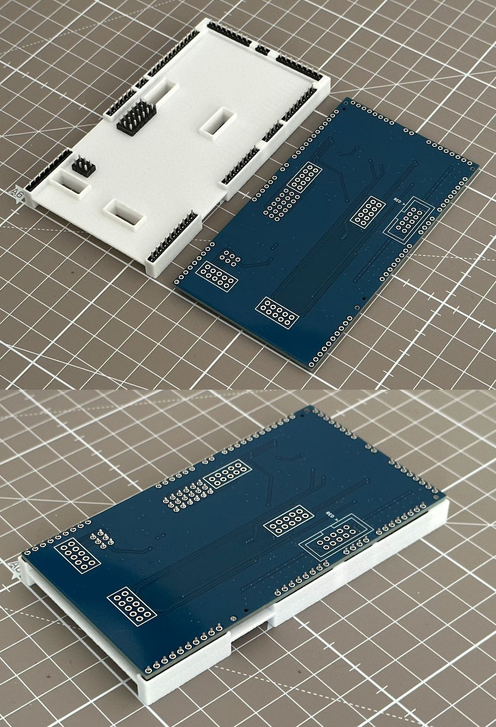
Put the soldering jig on a flat surface, then all the pin headers and sockets of the top side in their respective holes, and fit the board on top. Verify visually and if everything is proper, then solder all the pins.
Remove the board from the soldering jig, and turn over the soldering jig and the board. Then put the 4 5x2-position pin sockets, and fit the board on top. Verify visually and if everything is proper, then solder all the pins.
Remove the board from the soldering jig, and put the power 5x2 position pin headers.
Make sure the key of the pin header follows the orientation as shown on the PCB. If you look well on the picture above in the section “Using a Rubber Band”, the key is located on the left.
Double-check that the key of the pin header is in the right position ⚠️ and finally solder the pin header.
Finishing the Assembly

Finally put all the jumpers on the board.
For the 6-position headers, which are used for SD card reader, put them on the left of the pin headers, as shown in the picture. This selects the SD card connector on the kivu12 board itself.
For the 3-position headers, which are use to convert at most the first two CVs to pitch mode (0..10V), put them on the right of the pin headers. Putting CI1 and CI2 to bipolar mode (±5V) is important for later, because the two demo modules relies on this mode to be selected in order to function correctly.
Congratulations! Your kivu12 board is completed and waiting for your creations 🎉
Testing
At this point, you can connect the included 10pin-to-16pin header to the kivu12 motherboard, then to your rack, and power it up. At this stage, you should see a LED turning on on the Daisy Patch Submodule.