What is Eurorack-blocks?
How does it work?
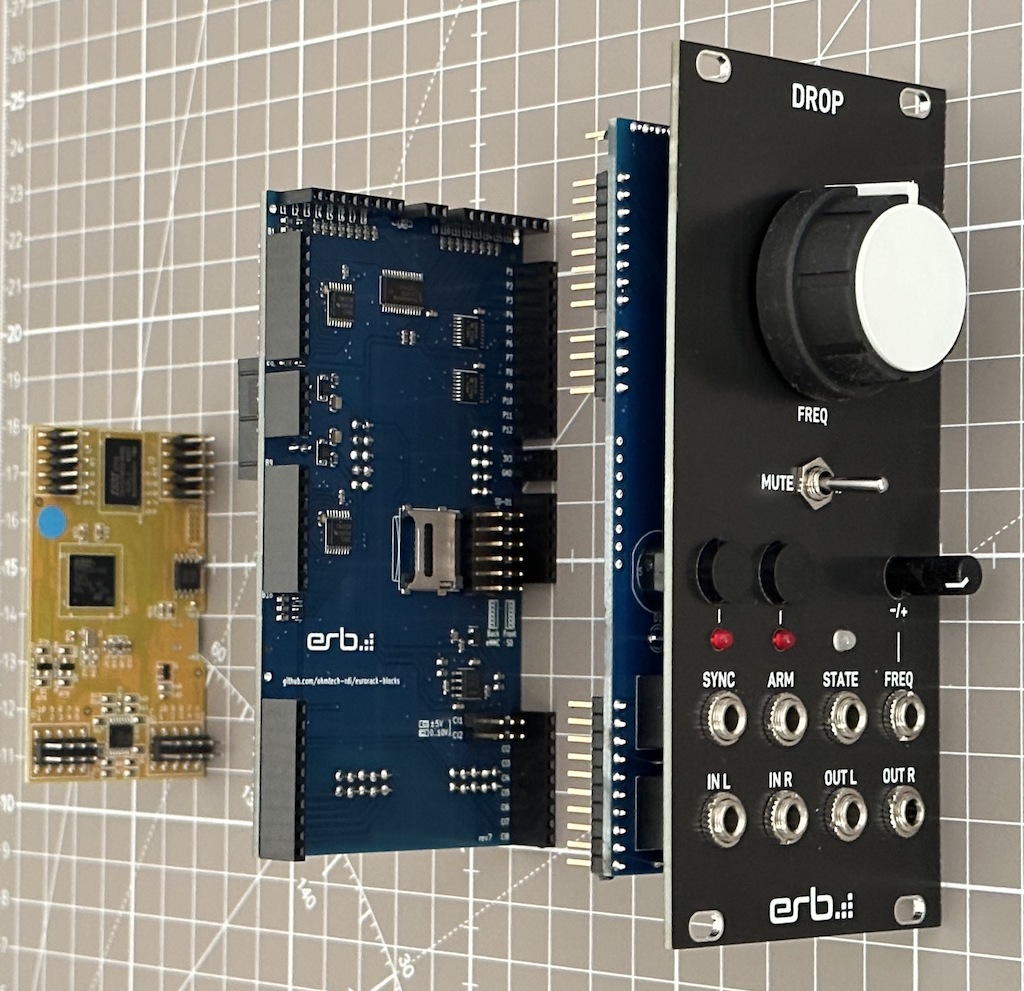
A finished Eurorack-blocks module is composed of 3 parts, from left to right:
The Daisy Patch Submodule, which hosts the processing unit on which your program executes,
The Eurorack-blocks back board, like
kivu12which mandates between the UI and the Daisy Patch Submodule, and extends the capabilities of the latter,The Eurorack-blocks front board, which presents the UI to your user, and is attached to the front aluminum panel using pots and jack connectors.
The back board like kivu12 can be reused from one module to another. You can assemble it yourself, but it can be also ordered from us (coming soon). A back board has a width in the standard Eurorack HP width, and front boards made for a back board needs to be at least as large as the back board. For example, if you use the 12HP kivu12 board, then your custom front board needs to be at least 12HP.
The back board also extends the capability of the Daisy Patch Submodule by giving more inputs and outputs.
For example, kivu12 delivers 12 Pots, 16 buttons or input gates, and 16 LED outputs, on top of the 2 audio inputs, 2 audio outputs, 8 CV inputs, 2 CV outputs, 2 Gate outputs and SD card that the Daisy Patch Submodule natively provides.
The front UI board is entirely generated by a configuration file that you create, using either the erbui language or the GUI editor (coming soon). Assembling the front board requires only very basic soldering skills.
The fully assembled module is sturdy and can be used for functional testing, and on the road. It is just a bit more deep than some other modules, so generally you want to avoid “skiff cases” during development.
But don’t worry! If you plan to make commercial modules, the custom modules are less deep and will fit in any Eurorack cases.
Workflow
Manufacturing the front board takes some time and money to produce. Once ordered, it probably takes around 2 weeks which are mainly waiting for your elements to be produced and/or sent, and most likely less than (but still) one hour to solder. Therefore iterating on the front board design this way would be a waste of time and money.
To accelerate this process and keep the creative flow uninterrupted, Eurorack-blocks allows you to simulate the module completely on your computer. This way, you have a quite good idea of what your module will be, and make drastic changes as you see fit: instead of taking weeks, iterations take a few seconds or minutes.
To make this possible, Eurorack-blocks uses a few principles:
The exact same code you produce will build for both the simulator and the firmware loaded on the Daisy Patch Submodule,
The simulator runs in VCV Rack, which allows to have a full setup to test your module with other modules, such as LFOs, triggers, oscilloscopes, etc.
There are only 3 parts in a typical project:
The
erbbmeta-build-system file, in which you dictate which files are part of your program,The
erbuiUI file, in which you dictate the layout of your module UI,One or more DSP files written in C++, Faust or done with Max.
That’s it! All the rest is automated for you.
Your Learning Journey
At its heart, Eurorack-blocks is a learning platform, allowing you to start from where you are to being able to make commercial modules and distribute them.
For this, we implemented baby steps, with success at each step, to keep you motivated while you learn. Here is the list of baby steps:
Level 1: Assembling the Starter Kit
Level 2: Making your first PCB order to a PCB manufacturer
Level 3: Routing your front board (can be combined with level 2 or not)
Level 4: Making a custom front panel design
At this stage, you will be able to make your own totally functional Eurorack modules. They won’t fit in every Eurorack “skiff” cases, and the production cost would be unsuitable to make a commercial product.
The next steps are to level up your game and become a professional Eurorack module manufacturer:
Level 5: Deriving kivu12 to combine back board and front board into one PCB
For this, you just need to copy our files, and remove what you don’t need to save a bit on costs. Routing will be also more challenging than in Level 3, but if you are comfortable with routing front boards in the previous steps, you will quickly learn to get something working.
Level 6: Custom boards
Level 5 gave you some understanding on how the electronics work in our project, and this level allows you to optimize production costs. At this level, you can already sell your creations.
Level 7: Mass production optimizations and distribution
This is the final level, where your module will be in retail shops. You will learn how to minimize manual labor work to scale your module for production, and at the same time keep a big enough gross margin to make your business sustainable, and be part of a global distribution network.